Top


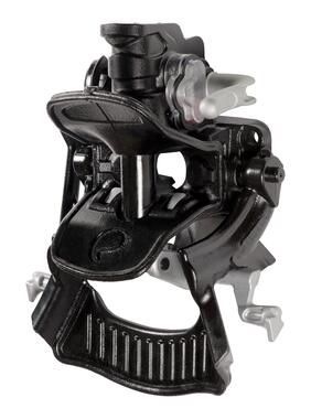
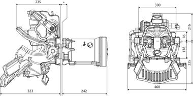
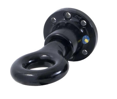
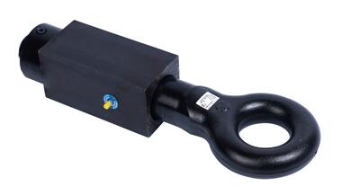
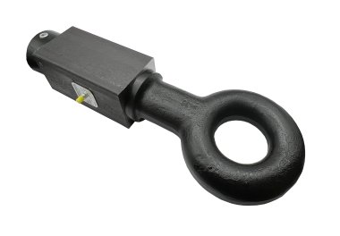
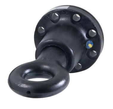
Coupling with guiding ramp
| Reference | Drawings | Documents |
|
D (kN) |
|
|
Dc (kN) | S (kg) | V (kN) |
|
|
Shock absorber | Tow bar thickness (*) | Bolt Ø /grade | Handles | Type | Draw |
|---|---|---|---|---|---|---|---|---|---|---|---|---|---|---|---|---|---|
| 2907644 |
Download |
63 | 200 | 103 | 50 | 160 | 1000 | 140 | 96 | 40 | 10-36 | M20 | D | G150 | |||
| 2907644L |
Download |
63 | 200 | 103 | 50 | 160 | 1000 | 140 | 96 | 40 | 10-36 | M20 | L | G150 | |||
| 2907646 |
Download |
74 | 200 | 103 | 50 | 160 | 1000 | 140 | 96 | 40 | AirConfort | 10-36 | M20 | D | G150 | ||
| 2907654 |
Download |
63 | 120 | 90 | 30 | 95 | 1000 | 36 | 87 | 24 | 8-36 | M16 | D | G145 | |||
| 2907654L |
Download |
63 | 120 | 90 | 30 | 95 | 1000 | 36 | 87 | 24 | 8-36 | M16 | L | G145 | |||
| 2907656L |
Download |
74 | 120 | 90 | 30 | 95 | 1000 | 36 | 87 | 24 | AirConfort | 8-36 | M16 | L | G145 | ||
| 2907646M |
Download |
74 | 200 | 103 | 50 | 160 | 1000 | 140 | 96 | 40 | AirConfort | 10-36 | M20 | D | G150M |
Reference
Drawings
Documents
D (kN)
Dc (kN)
S (kg)
V (kN)
Shock absorber
Tow bar thickness (*)
Bolt Ø /grade
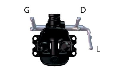
Handles
Type
Draw
2907644
63
200
103
50
160
1000
140
96
40
10-36
M20
D
G150
Reference
Drawings
Documents
D (kN)
Dc (kN)
S (kg)
V (kN)
Shock absorber
Tow bar thickness (*)
Bolt Ø /grade
Handles
Type
Draw
2907644L
63
200
103
50
160
1000
140
96
40
10-36
M20
L
G150
Reference
Drawings
Documents
D (kN)
Dc (kN)
S (kg)
V (kN)
Shock absorber
Tow bar thickness (*)
Bolt Ø /grade
Handles
Type
Draw
2907646
74
200
103
50
160
1000
140
96
40
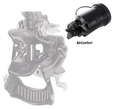
AirConfort
10-36
M20
D
G150
Reference
Drawings
Documents
D (kN)
Dc (kN)
S (kg)
V (kN)
Shock absorber
Tow bar thickness (*)
Bolt Ø /grade
Handles
Type
Draw
2907654
63
120
90
30
95
1000
36
87
24
8-36
M16
D
G145
Reference
Drawings
Documents
D (kN)
Dc (kN)
S (kg)
V (kN)
Shock absorber
Tow bar thickness (*)
Bolt Ø /grade
Handles
Type
Draw
2907654L
63
120
90
30
95
1000
36
87
24
8-36
M16
L
G145
Reference
Drawings
Documents
D (kN)
Dc (kN)
S (kg)
V (kN)
Shock absorber
Tow bar thickness (*)
Bolt Ø /grade
Handles
Type
Draw
2907656L
74
120
90
30
95
1000
36
87
24
AirConfort
8-36
M16
L
G145
Reference
Drawings
Documents
D (kN)
Dc (kN)
S (kg)
V (kN)
Shock absorber
Tow bar thickness (*)
Bolt Ø /grade
Handles
Type
Draw
2907646M
74
200
103
50
160
1000
140
96
40
AirConfort
10-36
M20
D
G150M
Related documents
Frequently asked questions
-
Your coupling system specifications can be found directly, on the label bonded onto the system, or in our catalogue.
-
The value D (expressed in kN), for a coupling system, is the maximum horizontal dynamic force generated by an articulated bar rig.
-
The value D (expressed in kN), for a coupling system, is the maximum horizontal dynamic force generated by a rig with central axles.
-
D = [(gross weight of trailer x max. loaded weight of carrier) / (gross weight of trailer x max. loaded weight of carrier)] x 9.81
-
Dc = [(gross weight of trailer x max. loaded weight of carrier) / (gross weight of trailer x max. loaded weight of carrier)] x 9.81
-
The value S (expressed in kg), for a coupling system, is the max. acceptable vertical static load. When preparing a load plan, this value must never be exceeded.
-
The value V (expressed in kN), for a coupling system, is the maximum acceptable vertical dynamic force generated by a rig with a central-axle trailer.
-
V = [gross weight of trailer x length of trailer platform x length of trailer platform x 2.4 (for a vehicle with mechanical suspension) or 1.8 (for a vehicle with pneumatic suspension)] / [total length from the ring to the trailer axle centre x total length from the ring to the trailer axle centre]
-
The initials BNA mean “Bureau de Normalisation de l’Automobile” (French standards authority for couplings in France).
-
A BNA hook is a fixed hook with a pin Ø 68 mm. A DIN hook is a rotary hook with a pin Ø 40 mm or 50 mm)
-
No, the two products are not compatible. If you have a BNA hook, it can only be coupled to a BNA ring. And similarly for a DIN hook.
-
The OF N° on a Pommier product is the manufacturing batch number. It comprises the year and week of manufacture, and the number of products manufactured.
-
The tightening torque values for your coupling are shown directly on the label bonded on the coupling, or in the coupling installation documentation.
-
A Spare Parts catalogue is available on our Web site, in PDF format. It will enable you to find all the spare parts available for most POMMIER products.
-
The part number of the KONEXO hook pin repair kit is: 2944034
-
No, unfortunately a manual hook cannot be converted to an automatic hook.
-
Yes, couplings can be painted. However, take care to ensure that the mechanisms remain functional and that the identity plate is still legible.
-
If the coupling system is approved R55, it is acknowledged as valid in all European Union countries. You can therefore use it everywhere in Europe.
-
If your KONEXO hook wasn’t initially equipped with a play compensation system, then unfortunately it cannot be retrofitted without work at our factory.
-
G145 and G150 are the between centres spacing for the drilled hook holes. G145 means a drilling spacing of 140x80 mm, and G150 means a drilling spacing of 160x100 mm.


