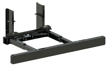
Hydraulic retractable underrun bar R58-03 with a fabricated U profile in steel. KTL finishing. Delivered assembled with hydraulic. The fabricated U profile allows the installation of reflective plates

Which products should you choose according to your needs?
| Reference | Drawings | Documents |
|
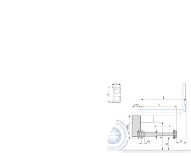
C | Cr | G-max | P-max | A-max | B_max | LG | Type |
|---|---|---|---|---|---|---|---|---|---|---|---|
| 29544222F |
Download |
136 | 502 | 102 | 450 > 550 | 300 | 979 > 1079 | 802 | 750 > 900 | Without detector | |
| 29544222FD |
Download |
136 | 502 | 102 | 450 > 550 | 300 | 979 > 1079 | 802 | 750 > 900 | With sensor | |
| 29544223F |
Download |
140 | 652 | 102 | 450 > 550 | 300 | 979 > 1079 | 952 | 750 > 900 | Without detector | |
| 29544223FD |
Download |
140 | 652 | 102 | 450 > 550 | 300 | 979 > 1079 | 952 | 750 > 900 | With sensor | |
| 29544224F |
Download |
145 | 921 | 102 | 450 > 550 | 300 | 979 > 1079 | 1221 | 750 > 900 | Without detector | |
| 29544224FD |
Download |
145 | 921 | 102 | 450 > 550 | 300 | 979 > 1079 | 1221 | 750 > 900 | With sensor | |
| 29544225F |
Download |
153 | 1201 | 102 | 450 > 550 | 300 | 979 > 1079 | 1501 | 750 > 900 | Without detector | |
| 29544225FD |
Download |
153 | 1201 | 102 | 450 > 550 | 300 | 979 > 1079 | 1501 | 750 > 900 | With sensor |
Reference
Drawings
Documents
C
Cr
G-max
P-max
A-max
B_max
LG
Type
29544222F
136
502
102
450 > 550
300
979 > 1079
802
750 > 900
Without detector
Reference
Drawings
Documents
C
Cr
G-max
P-max
A-max
B_max
LG
Type
29544222FD
136
502
102
450 > 550
300
979 > 1079
802
750 > 900
With sensor
Reference
Drawings
Documents
C
Cr
G-max
P-max
A-max
B_max
LG
Type
29544223F
140
652
102
450 > 550
300
979 > 1079
952
750 > 900
Without detector
Reference
Drawings
Documents
C
Cr
G-max
P-max
A-max
B_max
LG
Type
29544223FD
140
652
102
450 > 550
300
979 > 1079
952
750 > 900
With sensor
Reference
Drawings
Documents
C
Cr
G-max
P-max
A-max
B_max
LG
Type
29544224F
145
921
102
450 > 550
300
979 > 1079
1221
750 > 900
Without detector
Reference
Drawings
Documents
C
Cr
G-max
P-max
A-max
B_max
LG
Type
29544224FD
145
921
102
450 > 550
300
979 > 1079
1221
750 > 900
With sensor
Reference
Drawings
Documents
C
Cr
G-max
P-max
A-max
B_max
LG
Type
29544225F
153
1201
102
450 > 550
300
979 > 1079
1501
750 > 900
Without detector
Reference
Drawings
Documents
C
Cr
G-max
P-max
A-max
B_max
LG
Type
29544225FD
153
1201
102
450 > 550
300
979 > 1079
1501
750 > 900
With sensor
Related documents
Frequently asked questions
-
It’s version 03 of regulation N° 58 of the United Nations Economic Commission for Europe (CEE-ONU) – Unified directives relating to the approval of rear under-run protection systems (BAE)
-
Under-run bars are supplied complete, without the chassis mounting screws, available as an option.
-
The number of possible combinations (vehicle + accessories + body type) is infinite. You should check the feasibility yourself by downloading the 3D and the installation instructions.
-
Installation instructions can be downloaded from our Web site https://www.pommier.eu
-
The data sheets can be downloaded from our Web site https://www.pommier.eu
-
The approval report is confidential and is not available. However, on request, we can send it to the official authority (DREAL for example), which can request it directly from us.
-
Yes, depending on the model, when the bar is positioned. In general, the part of the arms protruding beyond the plate, and the part of the plate protruding beyond the arms do not contribute to the mechanical strength of our under-run bars, and can be cut off, in accordance with the installation instructions.
-
Grade 10.9 minimum. For the quantity, refer to the documentation.
-
Depending on the type of bar, it is authorised. See the documentation for greater detail.
-
I/V is the modulus of inertia. It’s a physical value related to the quadratic moment, used in the strength of materials to determine the maximum bending stress applied to a section of flexing beam.
It’s the quotient of the moment of inertia (I) by the distance of the extreme fibre at the axis passing through the centre of gravity (V). -
The quadratic moment is a value that describes the geometry of a section and is defined in relation to an axis or a point. It is expressed in the international system in m4 (metres to the power of 4). It expresses the relation to a point or to an axis, in particular to define the strength or distortion capability of a material.
The quadratic moment is used in materials’ strength. It is essential for the computing of the strength and distortion of beams subjected to torsion (IG) and bending (Ix and Iy) loads. In fact, the strength of a section loaded along a given axis varies with its quadratic moment along that axis. -
It’s the modulus of inertia (I/V) multiplied by the elastic limit of the material (Re)
-
All R58-03 under-run bars in our range are treated by cataphoresis, except for the XFIX P701AE, which is left raw as it is to be welded.
-
Yes. On under-run bars XFIX P61, XFIX S71, XFIX P70 and XLIFT P41, the round and square tube mounting clamps can be replaced by welding. This is mentioned in the installation documentation. Unless mentioned, it isn’t possible.
-
Yes, the under-run bar mounting screw kits are available as an option. See the documentation and catalogue.
-
Yes, providing the minimum of 100 mm remains on each side, measured between the inner faces of the tyres (not counting any tyre swelling due to ground contact). See installation documentation.
-
Under-run bars XPAND P42, XLIFT P72 and XFOLD P58 are assimilated to a quasi-machine and meet the essential requirements of the following sections of the machine directive: 1.1.3/ 1.1.5/ 1.2.6/ 1.3.1/1.3.6/ 1.5.3/ 1.5.8/ 1.5.9/ 1.6/ 1.7.
-
Yes, a user manual is available for non-fixed under-run bars. It is supplied with the under-run bar. It can also be downloaded from our Web site, in the “User documentation” section.
This document should be given to the under-run bar user, who should keep it. -
The min. and max. hydraulic pressures differ, depending on the dual valve model. These values are indicated in the installation documentation.
-
In mechanics, it’s the moment exerted to tighten a threaded assembly. It’s a force applied at the end of a moment arm of length L, that is expressed in Newton-metres (N.m.).
Tightening torque = force (F) x distance (L). In a prestressed assembly, the screw is subjected to tension and the assembled pieces to compression. The tightening torque values specified in our documentation must be respected. -
Cataphoresis, also known as electro-phoresis depositing (cationic electro-depositing), is a surface treatment that electro-chemically deposits an epoxy type base on a metal surface. The piece is immersed in a bath of water-soluble paint. The paint is electro-deposited by a DC current and is uniformly bonded on the piece, including in recesses and on sharp edges.
-
Salt spray resistance with no rust is 250 h on sharp edges and 500 h on plane surfaces.
-
Cataphoresis does not resist UV radiation. A paint finish should therefore be applied for any outdoor exposure. Cataphoresis is therefore frequently used, like a primer, to enhance corrosion resistance properties, or it may be used alone for non-visible parts (under vehicles, inside mechanisms and various machines, etc.).