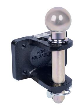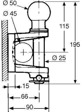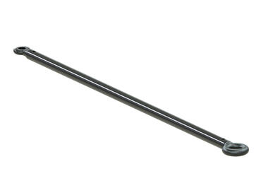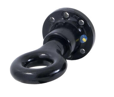

Towing jaw, delivered with bolt (*)
| Reference | Drawings | Documents |
|
D (kN) |
|
|
S (kg) |
|
|
Ø | Bolt Ø /grade | Type | Draw |
|---|---|---|---|---|---|---|---|---|---|---|---|---|---|
| 2905711 |
Download |
2,7 |
12 20 |
5 8,5 |
1.5 3,5 |
120 120 |
5 8,5 |
1.5 3,5 |
17 | * |
Sur boule Sur broche |
||
| 2905712 |
Download |
2,7 |
12 20 |
5 8,5 |
1.5 3,5 |
120 120 |
5 8,5 |
1.5 3,5 |
10,5 | M10 / 10.9 |
Sur boule Sur broche |
||
| 2905713 |
Download |
2,7 |
12 20 |
5 8,5 |
1.5 3,5 |
120 120 |
5 8,5 |
1.5 3,5 |
13 | M12/8.8 |
Sur boule Sur broche |
||
| 2905714 |
Download |
2,7 |
12 20 |
1.5 3,5 |
1.5 3,5 |
120 120 |
1.5 3,5 |
1.5 3,5 |
17 | * |
Sur boule Sur broche |
||
| 2905715 |
Download |
2,7 |
12 20 |
5 8,5 |
1,5 3,5 |
120 120 |
5 8,5 |
1,5 3,5 |
17 | M16/8.8 |
Sur boule Sur broche |
Reference
Drawings
Documents
D (kN)
S (kg)
Ø
Bolt Ø /grade
Type
Draw
2905711
2,7
12
20
20
5
8,5
8,5
1.5
3,5
3,5
120
120
120
5
8,5
8,5
1.5
3,5
3,5
17
*
Sur boule
Sur broche
Sur broche
Reference
Drawings
Documents
D (kN)
S (kg)
Ø
Bolt Ø /grade
Type
Draw
2905712
2,7
12
20
20
5
8,5
8,5
1.5
3,5
3,5
120
120
120
5
8,5
8,5
1.5
3,5
3,5
10,5
M10 / 10.9
Sur boule
Sur broche
Sur broche
Reference
Drawings
Documents
D (kN)
S (kg)
Ø
Bolt Ø /grade
Type
Draw
2905713
2,7
12
20
20
5
8,5
8,5
1.5
3,5
3,5
120
120
120
5
8,5
8,5
1.5
3,5
3,5
13
M12/8.8
Sur boule
Sur broche
Sur broche
Reference
Drawings
Documents
D (kN)
S (kg)
Ø
Bolt Ø /grade
Type
Draw
2905714
2,7
12
20
20
1.5
3,5
3,5
1.5
3,5
3,5
120
120
120
1.5
3,5
3,5
1.5
3,5
3,5
17
*
Sur boule
Sur broche
Sur broche
Reference
Drawings
Documents
D (kN)
S (kg)
Ø
Bolt Ø /grade
Type
Draw
2905715
2,7
12
20
20
5
8,5
8,5
1,5
3,5
3,5
120
120
120
5
8,5
8,5
1,5
3,5
3,5
17
M16/8.8
Sur boule
Sur broche
Sur broche
Related documents
Frequently asked questions
-
Your coupling system specifications can be found directly, on the label bonded onto the system, or in our catalogue.
-
The value D (expressed in kN), for a coupling system, is the maximum horizontal dynamic force generated by an articulated bar rig.
-
The value D (expressed in kN), for a coupling system, is the maximum horizontal dynamic force generated by a rig with central axles.
-
D = [(gross weight of trailer x max. loaded weight of carrier) / (gross weight of trailer x max. loaded weight of carrier)] x 9.81
-
Dc = [(gross weight of trailer x max. loaded weight of carrier) / (gross weight of trailer x max. loaded weight of carrier)] x 9.81
-
The value S (expressed in kg), for a coupling system, is the max. acceptable vertical static load. When preparing a load plan, this value must never be exceeded.
-
The value V (expressed in kN), for a coupling system, is the maximum acceptable vertical dynamic force generated by a rig with a central-axle trailer.
-
V = [gross weight of trailer x length of trailer platform x length of trailer platform x 2.4 (for a vehicle with mechanical suspension) or 1.8 (for a vehicle with pneumatic suspension)] / [total length from the ring to the trailer axle centre x total length from the ring to the trailer axle centre]
-
The OF N° on a Pommier product is the manufacturing batch number. It comprises the year and week of manufacture, and the number of products manufactured.
-
No, we do not authorise the installation of carrier systems on our Pommier ball hooks.
-
A Spare Parts catalogue is available on our Web site, in PDF format. It will enable you to find all the spare parts available for most POMMIER products.
-
Regulation R55 stipulates that the ball centre-line must be between 350 and 420 mm above the ground. Loaded vehicle. (Height range valid for M1 and N1 vehicles only).


